Sfd And Bmd Formulas : Shear Force Diagram Of A Simply Supported Beam With Triangular Load Distribution Engineering Stack Exchange. Tackle any project with this powerful and fast beam software. Below are the beam formulas and their respective sfd's and bmd's; 4.16 k 9.6 k 9.6 k 16 ft. Shear force and bending moment diagram of simply supported beam can be drawn by first calculating value of shear force and bending moment. Example on simply supported beam 7.
B cx shear and moment diagrams for frames let's start with member ab. A simply supported beam is the most simple arrangement of the structure. Bmd = bending moment diagram; In this video, i have explained how to draw shear force diagram (sfd) & bending moment diagram (bmd) for beam when uniformly distributed load (udl) & point l. When you design or analyze any structure then you have to consider the total shear force and bending moment to get the required strength and durability of the structure.
Simply Supported Udl Beam Formulas Bending Moment Equations Pdf Document from reader023.staticloud.net Ab is a beam of 10 feet length, point a is pin support & point b is roller support, a point load of 5 kip acts at the middle portion of the beam, then, Beam formulas with shear and moment diagrams. Add as many supports, loads, hinges and even additional members with skyciv paid plans. E = modulus of elasticity, psi or mpa Jalal afsar october 16, 2014 sfd & bmd no comments. As with all calculations care must be taken to keep consistent units throughout with examples of units which should be adopted listed below: Draw the afd, sfd and bmd of the beam bcd in the frame abcde loaded as shown below. Tackle any project with this powerful and fast beam software.
Shear force and bending moment diagram of simply supported beam can be drawn by first calculating value of shear force and bending moment.
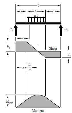
B cx shear and moment diagrams for frames let's start with member ab. Just use sagging = positive bending. 6 problems on afd, sfd, bmd of frames 1. Sfd = shear force diagram; 26 the positive sign convention consistent with beam theory is shown in f.1(b). Moment area method and castigliano's method. Fbd = free body diagram; Some more formulas important for gate, ese and psus. Bending moment calculation •for point load, calculate bending. Beam design formulas with shear and moment diagrams american forest & paper association w r v v 2 2 shear m max moment x design aid no. These above formulas are the necessary formulas for sfd & bmd which makes the calculation more easiest. Being able to draw shear force diagrams (sfd) and bending moment diagrams (bmd) is a critical skill for any student studying statics, mechanics of materials, or structural engineering. Since the problem is symmetrical reaction forces will be equal, and will be half of total.
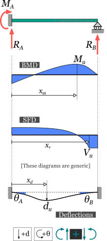
Bmd (bending moment diagram) is a diagram representing the variation of bending moment along the length of member.sfd (shear force diagram) is diagram representing variation of shear force along the length of structural member.we draw sfd and bmd to find the most critical position of loads that produces severe stress in the structural materials. In this video, i have explained how to draw shear force diagram (sfd) & bending moment diagram (bmd) for beam when uniformly distributed load (udl) & point l. As with all calculations care must be taken to keep consistent units throughout with examples of units which should be adopted listed below: A simply supported beam with uniformly distributed load. Which is a feature unavailable on most other.
Fixed One End Beam Pinned The Other Calcresource from cdn.calcresource.com Beam formulas with shear and moment diagrams. Some more formulas important for gate, ese and psus. Ab is a beam of 10 feet length, point a is pin support & point b is roller support, a point load of 5 kip acts at the middle portion of the beam, then, A simply supported beam is the most simple arrangement of the structure. Beamguru.com is a online calculator that generates bending moment diagrams (bmd) and shear force diagrams (sfd), axial force diagrams (afd) for any statically determinate (most simply supported and cantilever beams) and statically indeterminate beams, frames and trusses.the calculator is fully customisable to suit most beams, frames and trusses; A simply supported beam cannot have any translational displacements at its support points, but no restriction is placed on. Bendingmomentdiagram.com is a free online calculator that generates bending moment diagrams (bmd) and shear force diagrams (sfd) for most simple beams. B cx shear and moment diagrams for frames let's start with member ab.
Ab is a beam of 10 feet length, point a is pin support & point b is roller support, a point load of 5 kip acts at the middle portion of the beam, then,
Which is a feature unavailable on most other. When you design or analyze any structure then you have to consider the total shear force and bending moment to get the required strength and durability of the structure. A simply supported beam with uniformly distributed load. Moment area method and castigliano's method. As with all calculations care must be taken to keep consistent units throughout with examples of units which should be adopted listed below: There is a long way and a quick way to do them. Deflection of beams #3.2 : Included are simple bending moment equations and formulas which well help. Bending moment calculation •for point load, calculate bending. Just use sagging = positive bending. Sfd and bmd stand for the shear force diagram and the bending moment diagram applied to the structure respectively. Jalal afsar october 16, 2014 sfd & bmd no comments. An example will show you how all this works.
First step here would be determination of reaction forces. B cx shear and moment diagrams for frames let's start with member ab. All 3)for uniformly varying load load(uvl) the degree of curve is 2nd (parabola) in sfd and 3rd(cubic parabola) in bending moment diagram(bmd). Since the problem is symmetrical reaction forces will be equal, and will be half of total. Beam design formulas with shear and moment diagrams american forest & paper association w r v v 2 2 shear m max moment x design aid no.
Beam Formulas With Shear And Mom from www.linsgroup.com As with all calculations care must be taken to keep consistent units throughout with examples of units which should be adopted listed below: Thus m = boundary conditions gives m = 0 when x = 0 Bendingmomentdiagram.com is a free online calculator that generates bending moment diagrams (bmd) and shear force diagrams (sfd) for most simple beams. Fig.9 sfd and bmd of cantilever beam simply supported case: The calculator is fully customisable to suit most beams; Moment area method and castigliano's method. 26 the positive sign convention consistent with beam theory is shown in f.1(b). Tackle any project with this powerful and fast beam software.
Beam formulas with shear and moment diagrams.
Powerful hand calculation modules that show the step by step hand calculations (excluding hinges) for reactions, bmd, sfd, centroids, moment of inertia and trusses! American wood council the american wood council (awc) is part of the wood products group of the american forest & paper association (af&pa). A simply supported beam with uniformly distributed load. Ab is a beam of 10 feet length, point a is pin support & point b is roller support, a point load of 5 kip acts at the middle portion of the beam, then, Bmd (bending moment diagram) is a diagram representing the variation of bending moment along the length of member.sfd (shear force diagram) is diagram representing variation of shear force along the length of structural member.we draw sfd and bmd to find the most critical position of loads that produces severe stress in the structural materials. When you design or analyze any structure then you have to consider the total shear force and bending moment to get the required strength and durability of the structure. As seen from f.1 (b), the positive sign convention is (a) tension axial force, (b) shear forces that These above formulas are the necessary formulas for sfd & bmd which makes the calculation more easiest. Jalal afsar october 16, 2014 sfd & bmd no comments. 6 problems on afd, sfd, bmd of frames 1. B cx shear and moment diagrams for frames let's start with member ab. Example on simply supported beam 7. 26 the positive sign convention consistent with beam theory is shown in f.1(b).
Deflection of beams #32 : bmd sfd. In this video, i have explained how to draw shear force diagram (sfd) & bending moment diagram (bmd) for beam when uniformly distributed load (udl) & point l.
Share :
Post a Comment
for "Sfd And Bmd Formulas : Shear Force Diagram Of A Simply Supported Beam With Triangular Load Distribution Engineering Stack Exchange"


Post a Comment for "Sfd And Bmd Formulas : Shear Force Diagram Of A Simply Supported Beam With Triangular Load Distribution Engineering Stack Exchange"